Some Basic Concepts of Network Analysis
Basic Electrical Quantities
Electric Current (in a device) – designated by i(t), a function of time and is measured in amperes.
Electromotive Force (across a device) – designated by v(t), a function of time and is measured in volts.
Electric material can be broadly classified as: conductors and non-conductors (insulator).
The electric voltage across a perfect conductor must be zero and the electric current through a perfect insulator must be zero.
In network analysis we set these conditions mathematically by applying a short circuit (perfect conductor) and an open circuit (perfect insulator), respectively in the network.
3 types of diagrams to represent the network:
1. Pictorial schematic diagram – one that looks somewhat like the network represented.
2. Interconnection diagram – consists of a set of oriented line segments that indicate the pairs of points in the network at which measurements would be made to correspond with chosen network variables and that indicate the polarity of these measurements.
3. Schematic diagram – has the same geometry and orientation as a network interconnection diagram.
Instantaneous Meter – type of measuring instrument that we need to correlate with our analysis effort is one that, at least conceptually, has zero time lag in its motion and indicates both positive and negative values.
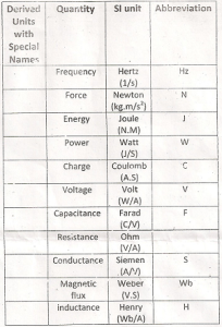
The international System of Units (SI) – commonly used in network analysis.

Resistance – the unit for resistance is ohm.
Kirchoff’s Law – principles postulated in 1847 by Gustav Kirchoff, a German physicist.
Kirchoff’s Current Law (KCL) – in any network, the oriented sum of instantaneous currents at each node is equal to zero.
Kirchoff’s Voltage Law (KVL) – in any electric network, the oriented sum of instanteneous voltage around every loop is equal to zero.
Kirchoff’s Current Law (Alternate Form) – the oriented sum of the instantaneous current at any supermode of a network is equal to zero.
